A History of Planning
I’ve been designing the AWRy since 1973, but my designs were always based on an HO scale railroad in whatever large space I could negotiate within our living quarters at the time. In 2014 when I took up N scale, I needed a major adjustment to my thinking and planning. It began with reading about what could be done in N scale, and then experimenting with sectional track and rolling stock. By the end of 2014 I had experimented and researched enough to have a good idea of the capabilities of this scale. I had also heard of building railroads on a hollow core door, so using AnyRail® track planning software I began trying various small layout ideas.
Graduating to larger spaces came quickly and over many months my plans evolved to room sized plans in the finished basement of our two-story home in West Michigan. During this time I also rejoined the operating crew of Bruce Chubb’s Sunset Valley Oregon System, a group I had been associated with in the 1980s and 1990s but lost touch with when I stepped away from model railroading in the mid-1990s. New experiences in railroad operations convinced me that just running trains was not going to be satisfying over the long term; operations had to be incorporated into the new plans for the AWRy. Armed with this information I came up with the classic “Givens and Druthers” list first proposed by John Armstrong, author of Track Planning for Realistic Operation.
And then, just to throw another wrench in the works, we moved! After 24 years in our single family home on a large lot, I decided I was ready to be done with the home and the yard (my wife had decided years ago), and trade it for a new spacious comfortable condo a couple of miles away, with a forest for a backyard, and access to a park on a large pond with walking trails. The best news was that the condo included a 17’ by 20’ storage room and connected utility room: in other words, a dedicated Train Room, subject of course to the approval of DW. With the move the question of transportability became another item on the Givens and Druthers list.
In most situations, the best use of space in a large layout room is an “around the walls” layout with a central peninsula. It provides the maximum amount of running distance for the available space and often provides an opportunity for multiple decks. This design also lends itself to the easy integration of T-Trak modules into the stretches along the walls and in the central peninsula. Since the central peninsula requires a turnback curve it could serve as the perfect location for T-Trak modules forming most of an oval. With the addition of two 90-degree corners the modules, when removed from the layout, could become a complete oval for display at shows and conventions.
Planning Arcadia Creek
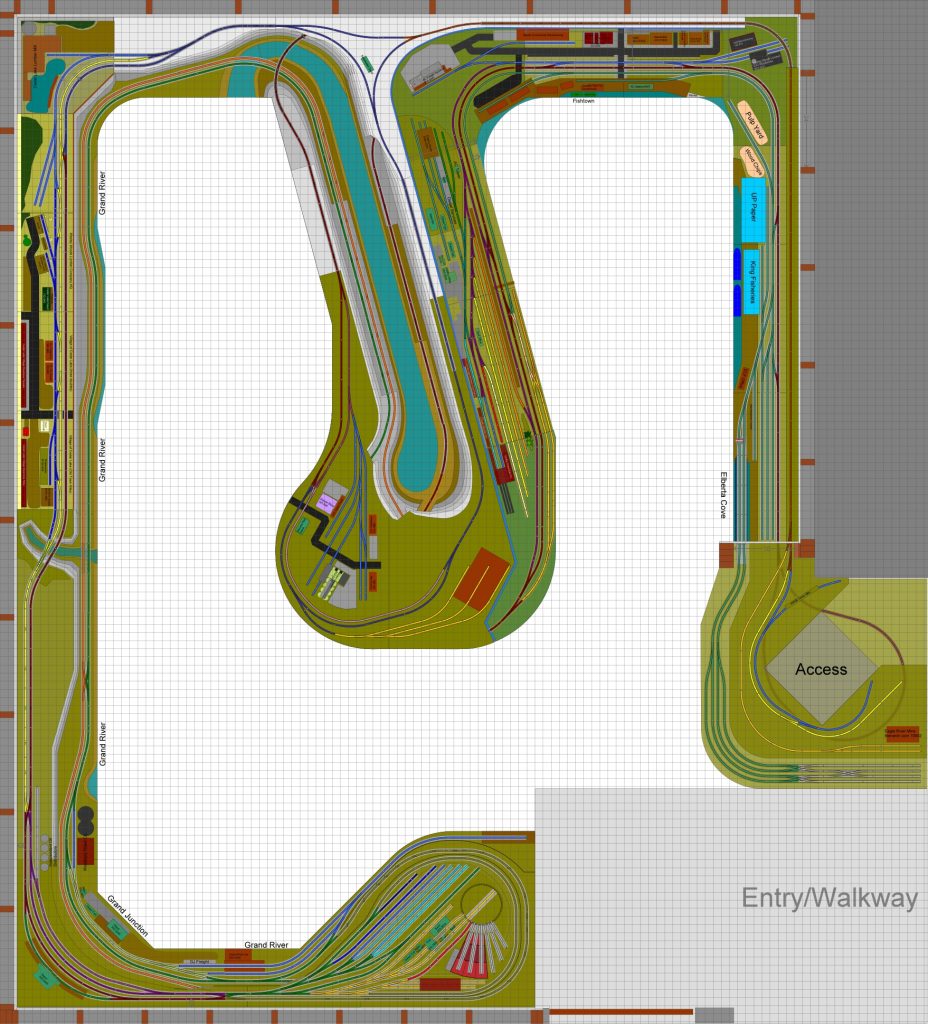
Given the features and advantages of the layout described above, and being desperate to get trains running again, I focused on designing a large layout with a central peninsula. The peninsula would be composed of T-Trak modules, removable to serve as a complete small and transportable layout. Once I had the general design of the overall layout the way I wanted it, I turned my attention to the details of the core T-Trak layout.
There were certain features I wanted in a beginning layout regardless of size, enough that I was willing to compromise scenic fidelity for functionality. I wanted a yard and engine facilities, industries for switching operations, a waterfront scene, and a little bit of city, as well as a continuous run option. The town of Skagway at the western/southern terminus of the White Pass and Yukon railway serves as inspiration for the town of Arcadia Creek on my railroad. It has a waterfront area and is the center of railroad operations for the railroad. There was not much rail served industry; the railroad served mostly to move people and supplies inland to the mines and ultimately to White Horse on the Yukon River.
With Arcadia Creek I envisioned a town larger than Skagway but with a similar beginning, whose growth led to more local rail served industry. Skagway was very linear, geographically speaking, but from a schematic view it was easy to wrap the stretch of track from the railroad or upper end of town around a curve into the city center and the waterfront area. Running track from the waterfront area back around to connect with the yard was an easy continuous run connection that made the peninsula a workable town location. This idea became the town of Arcadia Creek, my quick entry for operations and a great point for extending the Arcadia Creek and Woodbury Railway around the walls of the train room.
The next step in the planning process was to fit the track design to the standards in my Givens and Druthers list. Standard T-Trak corner modules use track radii of 282 and 315 millimeters requiring corners that measure 365 millimeters (about 14 1/3 inches) on a side. My standards call for track radii of 348 and 381 millimeters requiring corner modules measuring 431 millimeters or 17 inches. This became my standard depth for corner and straight modules and for shelf depths throughout the larger layout. With these basic dimensions I was able to design an oval layout that met my other requirements and would plug into my future room sized layout. The disadvantage of settling on this larger size is that the modules will only fit on a folding table if the adjustable feet are mounted four inches in from the front edge of the modules, a compromise I’m willing to make.
Turning to the question of how to quickly and efficiently get this core T-Trak module set into operation, the obvious answer was module kits. I already had very positive experiences with kits from Masterpiece Modules in Austin, Texas, but the modules required were not part of the set of standard modules Masterpiece or any other module kit maker offered.
I approached David Petersen at Masterpiece about custom module sizes and gave him the specs for the modules I needed. He suggested using his branchline modules as a starting point since they were 17 inches deep and triple the standard module width. He offered to engineer matching corner modules, but I determined that by removing a section from his branchline module I could create a 34 inch endcap or two 17 inch corners quite easily. I already planned to perform surgery to mount a turntable across modules so a little more fabrication will be no problem.
Masterpiece offers modules with either a flush deck or a deck recessed by one inch. The recessed deck modules are used when you want to extend scenery below track level. Because I’m modeling a waterfront scene representing an ocean coastline, I selected recessed decks for several of the modules. One inch equals thirteen feet four inches in N scale, a reasonable elevation from the midpoint between low and high tides which, in Skagway, run as much as seventeen feet from low to high.
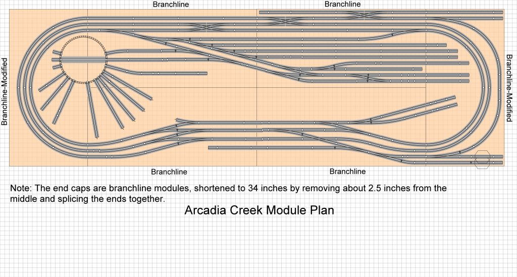
I also wanted the ability to switch out engine terminals for the two different periods I enjoy modeling. The recessed decks permit me to build terminals on one inch rigid foam insulation board which fits the recessed deck perfectly. Below is a picture of how the track plan lays out on the six modules.

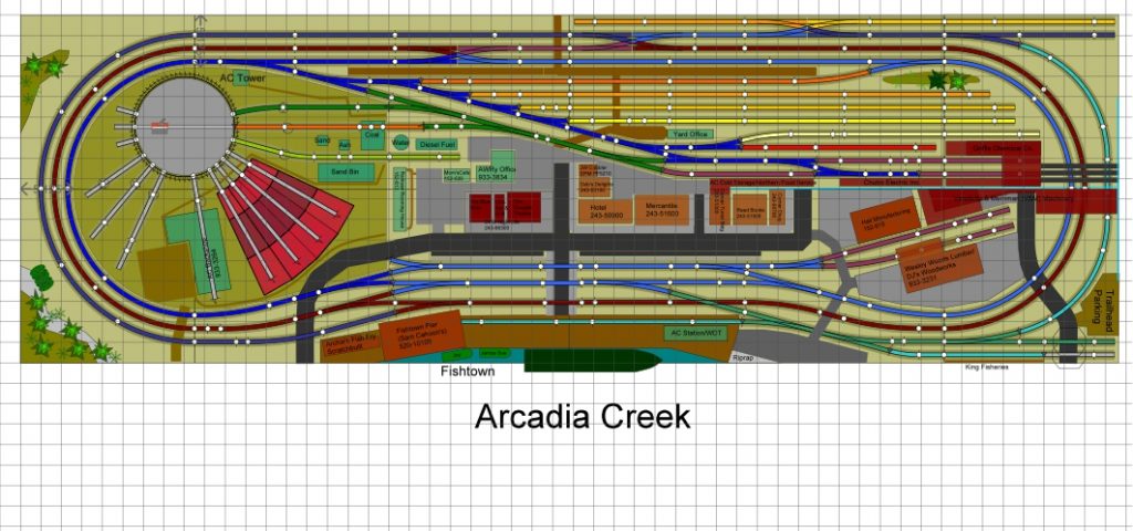
Here’s a view of the detailed plan representing the pre 1950 era:

The above plan addresses my desire for a transition era layout during which large steam and early diesel locomotives could be seen, and the double unit full cab diesels (FA and FB units) still required turning while coupled to reverse direction. The turntable can handle steam locomotives larger than 2-8-4 Berkshires and 4-8-4 Mountains, and F7A-B consists, as well as a switcher and two cars to service the sand, coal and oil docks.
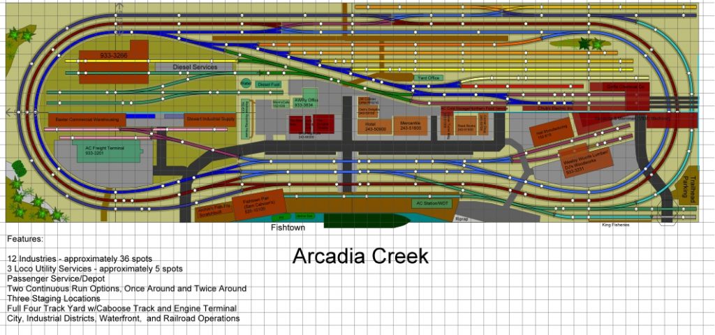
Here’s a view of the detailed plan with a modern diesel locomotive terminal:

This plan updates us to the post 1970 era with a terminal that can handle large six axle diesel locomotives, while providing three more industries with 8 more spots.
You may be wondering how I produce these drawings and plans. I use software called AnyRail®, for which I paid a one-time license fee. It has a huge library of commercial track in all scales, many structure objects and other scenery objects, as well as many objects uploaded by the user community. Here’s an example of the detail that can be included. It can also show elevations and part numbers for track.

More about AnyRail® can be found here.

Comments
My Planning Process — No Comments
HTML tags allowed in your comment: <a href="" title=""> <abbr title=""> <acronym title=""> <b> <blockquote cite=""> <cite> <code> <del datetime=""> <em> <i> <q cite=""> <s> <strike> <strong>